
Fault Models in DFT: A Comprehensive Guide to the Different Types of Fault Models in DFT
Engineers use methods called Design for Testability (DFT) to do this. DFT techniques make testing and figuring out what’s wrong with circuits easy. DFT uses strategies and tools, like fault modelling and automatic test pattern generation (ATPG), to find problems early in the design process.
Design for Testability (DFT) is utilized in digital system design to simplify circuit testing and discover the majority of problems. One key element of DFT is using a fault version, which categorizes distinct types of faults inside the design.
These fault models describe the types of physical defects that can exist in the design and guide the Automatic Test Pattern Generation (ATPG) tool in creating test vectors.
A fault model provides a specific categorization of faults in the design, which helps the ATPG tool generate targeted test vectors based on the selected fault model by ensuring that the tests are comprehensive and effectively detect possible faults in the system.
In the context of testing and DFT:
DEFECT: Refers to any unexpected difference between an electronic system’s designed and implemented hardware, which may arise from manufacturing variations or other physical issues.
FAULT: Represents a logical abstraction of a defect, providing a higher-level understanding of the problem.
ERROR: Occurs when a fault leads to incorrect outputs in the system.
By Utilizing fault models, the ATPG tool can generate specific test vectors tailored to the expected faults, allowing for more efficient and targeted testing.
Types of Fault Model in DFT
1. Stuck at Fault Model
a) Stuck at One
b) Stuck at Zero
2. Delay Fault Models
a) Transition Delay Fault
b) Path Delay Fault
3. Bridging Fault Model
4. IDDQ Fault Model
1. STUCK AT FAULT MODEL
Stuck-at-fault models are categorized into two types:
One is stuck at one fault, and another is stuck at the zero fault model.
Stuck-At-One Fault:
In this model, a net within a logic gate is shorted with the power supply, causing the node to behave like it is always in a high state.

Fig: Stuck at one fault
Stuck-At-Zero Fault:
Conversely, this model involves a net being shorted to ground, resulting in the node remaining at a low state.
The stuck-at-fault model is defined as a physical type of fault exhibited compared to Transition delay fault modeling.

Fig: Stuck at zero fault
In this way, we can detect those stuck at fault using the test patterns generated by the ATPG Tool.
2. DELAY FAULT MODEL
1. Transition Delay Fault
Delay faults simulate defects affecting a circuit’s timing performance. Two commonly used delay fault models are the transition delay fault and path delay fault models.
A transition delay fault occurs in a digital design when any combinational logic’s input or output node fails to transition its signal value within the predetermined time frame.

Fig: Transition Fault
2. Path Delay Fault
In the path delay fault model, a circuit is considered faulty if any of its paths experience a delay exceeding the specified threshold.Transitions are applied at the start of the path to detect delay defects on a path and observe how signals propagate through it.
One limitation of path delay fault testing is the large number of paths in a circuit.
A common strategy is to focus on testing paths with delays more significant than the specified threshold or clock period. This approach prioritizes longer or critical paths, as defects in shorter paths may not significantly affect the circuit’s behavior.
If a defect in a shorter path does impact performance, it can typically be detected through transition fault testing.
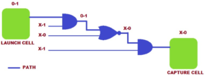
Fig: Path Delay Testing
3. BRIDGING FAULT MODEL
For example, two nets may create a “wired-OR” or “wired-AND” configuration, causing incorrect circuit behavior.
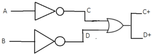
INPUTS C D | WIRED OR C+ D+ |
0 0 | 0 0 |
0 1 | 1 1 |
1 0 | 1 1 |
1 1 | 1 1 |
Fig: WIRED OR
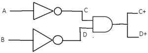
INPUTS C D | WIRED AND C+ D+ |
0 0 | 0 0 |
0 1 | 0 0 |
1 0 | 00 |
1 1 | 1 1 |
Fig: WIRED AND
4. IDDQ FAULT MODEL
Introduction to IDDQ Testing
CMOS (Complementary Metal Oxide Semiconductor) circuits operate with low power consumption under static conditions. IDDQ testing measures the power supply current in a static CMOS circuit.
CMOS working principle is as follows:
● When the input voltage (Vin) is 0, the PMOS transistor is ON, and the NMOS transistor is OFF.
● When the input voltage (Vin) is 1, the NMOS transistor is ON, and the PMOS transistor is OFF.

Fig: CMOS INVERTER SCHEMATIC
What Is the IDDQ Test?
IDDQ, or Quiescent Direct Drain Current, is a test that measures the current drawn from the power delivered when a CMOS circuit is in a static state (i.e., no longer actively switching). This test helps identify problems in a circuit, including leakage currents or dynamic circuits, that could indicate the presence of faults.
In static conditions, CMOS circuits have the advantage of very low power consumption because leakage currents are minimal. During active switching states, the circuit only consumes a significant amount of current from the power supply.
Why is there an IDDQ Test?
The IDDQ test was introduced as an alternative to voltage testing because generating test patterns for voltage testing can be complex and time-consuming.
IDDQ testing makes the process easier by measuring the current that a circuit draws when it is not static. This lets problems like leaking currents or short circuits be found.
This method makes circuits more reliable by quickly finding and fixing possible problems.

Fig: CMOS Inverter Schematic
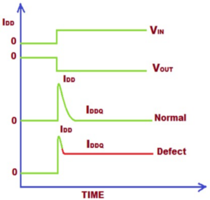
Fig :Voltage and Current
IDDQ Test Process
The IDDQ test process measures the total power supply current when both PMOS and NMOS transistors in a CMOS circuit are static.
The regular, fault-free power supply current is usually in the micro-amp range for small and medium-sized CMOS circuits. A low-resistance path forms in the circuit when a fault occurs, such as a bridging or gate-source short circuit.This causes the total power supply current to increase, sometimes reaching the milli-amp range.
The IDDQ test principle detects leakage current in the CMOS circuit when it is in a static state. Under normal conditions, the static current is very low but will be significantly higher if a defect occurs. If the measured current from a circuit using the IDDQ method is outside the normal range, it indicates a potential defect in the circuit.
The IDDQ test relies on measuring static current and typically includes a waiting period after applying each IDDQ test pattern before taking measurements. As a result, the test speed is relatively slow.
Conclusion
Understanding the various types of fault models in DFT is essential for effective testing and ensuring the reliability of VLSI designs. From stuck-at faults to delay and bridging faults, each model offers a unique perspective on potential issues within circuits.
By using these models, engineers can generate precise test patterns that identify and address faults early in the design process. The importance of DFT and fault modeling will go as technology advances

